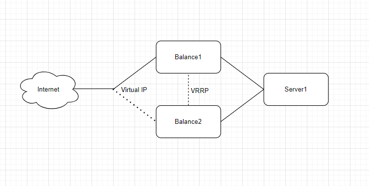
VRRP – Virtual Redundancy Routing Protocol in Linux systems could be implemented with keepalived.
Also, keepalived could be used to implement High Availability (active/passive) or load balancing (active/active).
Four aspects need to be configured on a VRRP HA server: keepalived, iptables, sysctl and the service itself (rsyslog in this case).
Sysctl.
The host’s kernel needs to be configured to allow a process to bind to a non-local IP address and enable ip routing.
# in /etc/sysctl.conf or similar
net.ipv4.ip_nonlocal_bind=1
net.ipv4.ip_forward = 1
Keepalived.
Sample configuration for Keepalived at server Balance1.
vrrp_instance VI_S1 {
        state MASTER   # (optional) initial state for this server
        interface eth1 # interface where VRRP traffic will exist
        advert_int 5   # how often we will vote (sec).
        virtual_router_id 71 # unique identifier per VRRP instance (same across all servers on the instance)
        priority 100   # server priority - higher number == higher priority

        # authentication for VRRP messages
        authentication {
                auth_type PASS # simple authentication (plain)
                #auth_type AH    # good authentication
                auth_pass super_secure_password # password
        }
        virtual_ipaddress {
                10.10.10.10/24 dev eth0 # Virtual IP address and interface assignment
}
        track_script {
                check_rsyslog # tracking script
        }
vrrp_script check_rsyslog {
        script "/usr/local/sbin/checkrsyslog.sh"
        interval 5 # 5s per check
        fall 2 # 2 fails - 10s
        rise 2 # 2 OKs - 10s
        #timeout 15 # wait up to 15 seconds for script before assuming fail
        #weight 50 # Reduce priority by 10 on fall
}
Notes:
VRRP instance will start as MASTER, meaning it will be an active server.
VRRP traffic will go via eth1 interface. We can use other interfaces, including same interface on what Virtual IP live.
virtual_router_id and authentication must match across all nodes in the VRRP instance.
track_script, defined under ‘vrrp_script check_rsyslog’ points to a custom script that checks whether the HA service is live. If the script returns any value other than 0, the HA service is seems failed and the node will remove itself from the pool of eligible hosts that can be active. If it was the active server, then another node will become active.
Iptables.
iptables needs to be configured in a way that the server accepts incoming traffic on the VRRP interface (eth1 in the sample configuration) from the other VRRP instance nodes under protocols VRRP or AH respectively for auth_type PASS or AH:
-A <CHAIN> -s <OTHER_VRRP_INSTANCE_NODES> -p vrrp -j ACCEPT
-A <CHAIN> -s <OTHER_VRRP_INSTANCE_NODES> -p ah -j ACCEPT
Service.
Finally, the service needs to be setup to listen on the Virtual IP interface, in this case rsyslog was configured to bind to all interfaces.
And, of course we need to start keepalived service.
Sample configuration for Keepalived at server Balance2.
Configuration foe second server almost identical to server Balance1 with slight difference in keepalived configuration (indicate initial state as Backup and decreased priority to make sure this server will be backup server).
Here configuration fragment with differences:
vrrp_instance VI_S1 {
        state BACKUP   # (optional) initial state for this server
        interface eth1 # interface where VRRP traffic will exist
        advert_int 5   # how often we will vote (sec).
        virtual_router_id 71 # unique identifier per VRRP instance (same across all servers on the instance)
        priority 50   # server priority - higher number == higher priority
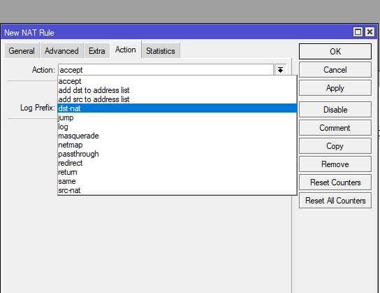
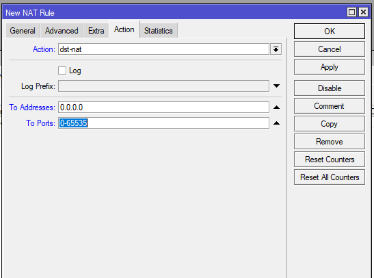
Case: Customer concerns about firewall configuration. Firewall implemented on Linux server. Firewall includes NAT.
Discovery: During review of firewall configuration I discovered following – total number of lines in configuration are ~5500. Some rules grouped in groups (chains). Some groups have no rules in them. Many rules never have had traffic passing through them.
Advice stage 1: Remove empty groups. Remove rules with no traffic passing through them. Create cpecific group for DROP rules.
Result of stage 1: reduction of lines in firewall configuratio to ~850 lines.
Advice stage 2: Migrate from per-host configuration to per-network configuration.
Results of stage 2: reduction of lines in firewall configuration to ~300 lines.
Case: Customer have appliance from vendor running Linux. Customer have no access (restricted by agreement with vendor) to scheduler on server. Customer want periodically gather some information from applience and use it.
Solution: Create shell script on Linux server, owned by customer. Schedule it on customers server. In mentioned script use remote execution to gather required information from applience.
What script do: connect to remoter server via ssh and port 2022. Use user1 and pass1 to authenticate during this process. On remote server gain root-leve access with sudo command and password pass2. Execute python script on remote server and select only some rows from feedback and transfer them to local server. Get selected data and strip it from unnesessary columns. Save data to file.
Customer have one big network with all users in same network fragment. Customer want to improve security.
Problem description: All employee reside in one big network fragment and have some level of access to all corporate servers. Production and support team span acros entire building.
Proposed solution: Split network in 4 fragments: servers, support, production and management. Restrict access to corporate servers with Fortigate firewall. Restrict access to corporate resources with access groups at AD.
Initial schematic (fragment of network).
Implemented solution schematic (fragment of solution).
Note: Port-channel and spanning-tree were used for inter-switch connection for redundancy.
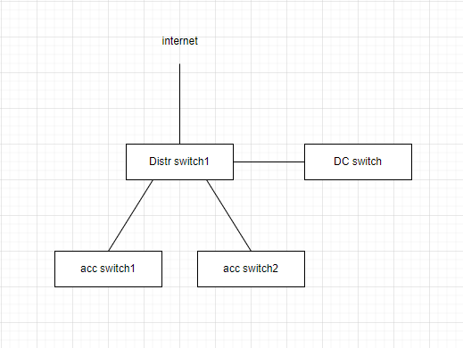
Customer have issues with LAN. Customer do not want to spend money on new switches/routeres. Bottleneck – connection between datacenter switches and distribution/access level switches.
Problems description: low througput. No redundancy for access switches 1 & 2 for cases, when link from access witch to distribution switch fail.
Proposed solution: increase througput between DC switches and distibution level switches. Increase througput between distribution switches and access level switches. Introduce redundancy.
Initial schematic (fragment of network).
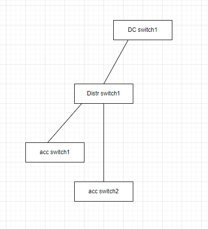
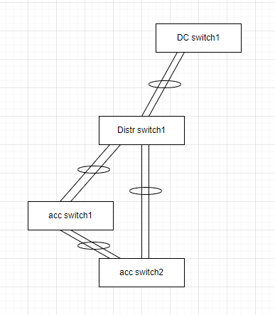
Implemented solution schematic (fragment of solution).
Solution description: Impement port-channel connection between DC switch 1 and distribution switch1. Implement port-channel connection between Distribution switch 1 anc access switches 1 & 2. Connect access switches 1 & 2 with port-channnel. Configure spanning tree, to make sure Distr switch will be root bridge.
Configuration fragments.
DC switch 1:
interface Port-channel14
  description Port-Channel to Distr switch 1

interface Ethernet0/1
  description Link to Distr switch 1
  switchport
  switchport mode trunk
  channel-group 14 mode active
interface Ethernet0/2
  description Link to Distr switch 1
  switchport
  switchport mode trunk
  channel-group 14 mode active
interface Ethernet0/3
  description Link to Distr switch 1
  switchport
  switchport mode trunk
  channel-group 14 mode active
interface Ethernet0/4
  description Link to Distr switch 1
  switchport
  switchport mode trunk
  channel-group 14 mode active
Distr switch 1:
spanning-tree vlan 10-500 priority 28672

interface Port-channel14
  description Port-Channel to DC switch 1

interface Port-channel56
  description Port-Channel to DC switch 1

interface Port-channel78
  description Port-Channel to DC switch 1

interface Ethernet0/1
  description Link to DC switch 1
  switchport
  switchport mode trunk
  channel-group 14 mode active
interface Ethernet0/2
  description Link to DC switch 1
  switchport
  switchport mode trunk
  channel-group 14 mode active
interface Ethernet0/3
  description Link to DC switch 1
  switchport
  switchport mode trunk
  channel-group 14 mode active
interface Ethernet0/4
  description Link to DC switch 1
  switchport
  switchport mode trunk
  channel-group 14 mode active

interface Ethernet0/5
  description Link to acc switch 1
  switchport
  switchport mode trunk
  channel-group 56 mode active
interface Ethernet0/6
  description Link to acc switch 1
  switchport
  switchport mode trunk
  channel-group 56 mode active

interface Ethernet0/7
  description Link to acc switch 2
  switchport
  switchport mode trunk
  channel-group 78 mode active
interface Ethernet0/8
  description Link to acc switch 2
  switchport
  switchport mode trunk
  channel-group 78 mode active
Acc switch 1
interface Port-channel12
  description Port-Channel to Distr switch 1

interface Port-channel34
  description Port-Channel to acc switch 2


interface Ethernet0/1
  description Link to Distr switch 1
  switchport
  switchport mode trunk
  channel-group 12 mode active
interface Ethernet0/2
  description Link to Distr switch 1
  switchport
  switchport mode trunk
  channel-group 12 mode active

interface Ethernet0/3
  description Link to acc switch 2
  switchport
  switchport mode trunk
  channel-group 34 mode active
interface Ethernet0/4
  description Link to acc switch 2
  switchport
  switchport mode trunk
  channel-group 34 mode active
Acc switch 2
interface Port-channel12
  description Port-Channel to Distr switch 1

interface Port-channel34
  description Port-Channel to acc switch 1


interface Ethernet0/1
  description Link to Distr switch 1
  switchport
  switchport mode trunk
  channel-group 12 mode active
interface Ethernet0/2
  description Link to Distr switch 1
  switchport
  switchport mode trunk
  channel-group 12 mode active

interface Ethernet0/3
  description Link to acc switch 1
  switchport
  switchport mode trunk
  channel-group 34 mode active
interface Ethernet0/4
  description Link to acc switch 1
  switchport
  switchport mode trunk
  channel-group 34 mode active
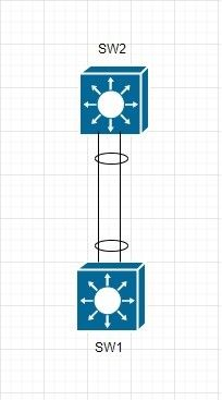
Port-Channel – is a bundle of 2+ links between 2 switches (see example below). Links bundled together and connection utilize throughput of both links. In comparison to spanning tree, links utilization become more efficient, as both links are used for data transfer.
Sample configuration.
Sw1
interface Port-channel12
  description Port-Channel to SW2

interface Ethernet0/1
  description Link to SW2
  switchport
  switchport mode trunk
  channel-group 12 mode active
interface Ethernet0/2
  description Link to SW2
  switchport
  switchport mode trunk
  channel-group 12 mode active
Sw2
interface Port-channel21
  description Port-Channel to SW1

interface Ethernet0/1
  description Link to SW1
  switchport
  switchport mode trunk
  channel-group 21 mode active
interface Ethernet0/2
  description Link to SW1
  switchport
  switchport mode trunk
  channel-group 21 mode active
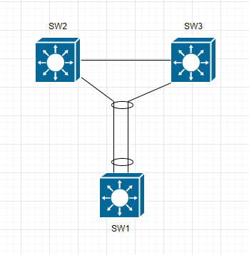
Virtual Port-Channel – same as Port-Channel, with single difference – link on one side of VPC goes to two switches (see example below).