Case: improve resilency and throughput of network.

Customer have issues with LAN. Customer do not want to spend money on new switches/routeres. Bottleneck – connection between datacenter switches and distribution/access level switches.

Problems description: low througput. No redundancy for access switches 1 & 2 for cases, when link from access witch to distribution switch fail.

Proposed solution: increase througput between DC switches and distibution level switches. Increase througput between distribution switches and access level switches. Introduce redundancy.

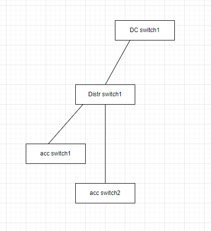
Initial schematic (fragment of network).

Implemented solution schematic (fragment of solution).

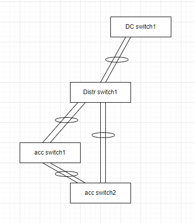
Solution description: Impement port-channel connection between DC switch 1 and distribution switch1. Implement port-channel connection between Distribution switch 1 anc access switches 1 & 2. Connect access switches 1 & 2 with port-channnel. Configure spanning tree, to make sure Distr switch will be root bridge.

Configuration fragments.

DC switch 1:

interface Port-channel14
  description Port-Channel to Distr switch 1
 
interface Ethernet0/1
  description Link to Distr switch 1
  switchport
  switchport mode trunk
  channel-group 14 mode active
interface Ethernet0/2
  description Link to Distr switch 1
  switchport
  switchport mode trunk
  channel-group 14 mode active
interface Ethernet0/3
  description Link to Distr switch 1
  switchport
  switchport mode trunk
  channel-group 14 mode active
interface Ethernet0/4
  description Link to Distr switch 1
  switchport
  switchport mode trunk
  channel-group 14 mode active

Distr switch 1:

spanning-tree vlan 10-500 priority 28672

interface Port-channel14
  description Port-Channel to DC switch 1
 
interface Port-channel56
  description Port-Channel to DC switch 1

interface Port-channel78
  description Port-Channel to DC switch 1

interface Ethernet0/1
  description Link to DC switch 1
  switchport
  switchport mode trunk
  channel-group 14 mode active
interface Ethernet0/2
  description Link to DC switch 1
  switchport
  switchport mode trunk
  channel-group 14 mode active
interface Ethernet0/3
  description Link to DC switch 1
  switchport
  switchport mode trunk
  channel-group 14 mode active
interface Ethernet0/4
  description Link to DC switch 1
  switchport
  switchport mode trunk
  channel-group 14 mode active

interface Ethernet0/5
  description Link to acc switch 1
  switchport
  switchport mode trunk
  channel-group 56 mode active
interface Ethernet0/6
  description Link to acc switch 1
  switchport
  switchport mode trunk
  channel-group 56 mode active

interface Ethernet0/7
  description Link to acc switch 2
  switchport
  switchport mode trunk
  channel-group 78 mode active
interface Ethernet0/8
  description Link to acc switch 2
  switchport
  switchport mode trunk
  channel-group 78 mode active

Acc switch 1

interface Port-channel12
  description Port-Channel to Distr switch 1
 
interface Port-channel34
  description Port-Channel to acc switch 2


interface Ethernet0/1
  description Link to Distr switch 1
  switchport
  switchport mode trunk
  channel-group 12 mode active
interface Ethernet0/2
  description Link to Distr switch 1
  switchport
  switchport mode trunk
  channel-group 12 mode active

interface Ethernet0/3
  description Link to acc switch 2
  switchport
  switchport mode trunk
  channel-group 34 mode active
interface Ethernet0/4
  description Link to acc switch 2
  switchport
  switchport mode trunk
  channel-group 34 mode active

Acc switch 2

interface Port-channel12
  description Port-Channel to Distr switch 1
 
interface Port-channel34
  description Port-Channel to acc switch 1


interface Ethernet0/1
  description Link to Distr switch 1
  switchport
  switchport mode trunk
  channel-group 12 mode active
interface Ethernet0/2
  description Link to Distr switch 1
  switchport
  switchport mode trunk
  channel-group 12 mode active

interface Ethernet0/3
  description Link to acc switch 1
  switchport
  switchport mode trunk
  channel-group 34 mode active
interface Ethernet0/4
  description Link to acc switch 1
  switchport
  switchport mode trunk
  channel-group 34 mode active

Upgrade OS on NEXUS switch from v6 to v9

There is no option to direct upgrade from v6 to v9. Following steps allow this happens. Remember memory limits and use smaller image, if you need to.

Copy new image to switch.

copy usb1:n3000-uk9-kickstart.6.0.2.U6.10.bin bootflash:
copy usb1:n3000-uk9.6.0.2.U6.10.bin bootflash:
copy usb1:nxos.7.0.3.I6.1.bin bootflash:

Install image.

install all kickstart bootflash:n3000-uk9-kickstart.6.0.2.U6.10.bin system bootflash:n3000-uk9.6.0.2.U6.10.bin

remove old image

delete bootflash:n3000-uk9-kickstart.6.0.2.U6.6.bin
delete bootflash:n3000-uk9.6.0.2.U6.6.bin

Install v7 image.

install all nxos bootflash:nxos.7.0.3.I6.1.bin

delete old images

delete bootflash:n3000-uk9*

Copy v9 image

copy usb1:nxos.9.3.8.bin bootflash:

do some configuration change

conf t
no system dme enable
end
copy run start

Install v9.

install all nxos bootflash:nxos.9.3.8.bin

Port-channel (PC) / Virtual port-channel (VPC)

Port-Channel – is a bundle of 2+ links between 2 switches (see example below). Links bundled together and connection utilize throughput of both links. In comparison to spanning tree, links utilization become more efficient, as both links are used for data transfer.

Sample configuration.

Sw1

interface Port-channel12
  description Port-Channel to SW2
 
interface Ethernet0/1
  description Link to SW2
  switchport
  switchport mode trunk
  channel-group 12 mode active
interface Ethernet0/2
  description Link to SW2
  switchport
  switchport mode trunk
  channel-group 12 mode active

Sw2

interface Port-channel21
  description Port-Channel to SW1
 
interface Ethernet0/1
  description Link to SW1
  switchport
  switchport mode trunk
  channel-group 21 mode active
interface Ethernet0/2
  description Link to SW1
  switchport
  switchport mode trunk
  channel-group 21 mode active

Virtual Port-Channel – same as Port-Channel, with single difference – link on one side of VPC goes to two switches (see example below).

This feature LIMITED to some switch models.

Sample configuration.

SW1

interface port-channel 10
  description Port-channel-To-SW2-and-SW3

interface Ethernet1/1
  description link-To-SW2
  switchport mode trunk
  switchport trunk allowed vlan 10,20
  channel-group 10 mode active

interface Ethernet1/2
  description link-To-SW3
  switchport mode trunk
  switchport trunk allowed vlan 10,20
  channel-group 10 mode active

Sw2

vrf context vpc_keepalive

interface port-channel 10

  description Port-channel-To-SW1
  vpc 1

interface Ethernet1/49
  description VPC Keepalive link
  ip address 10.255.255.1/30
  no shu
  
interface Ethernet1/1
  description link-To-SW1
  switchport mode trunk
  switchport trunk allowed vlan 10,20
  spanning-tree port type edge trunk
  channel-group 10 mode active

vpc domain 1
  role priority 1
  peer-keepalive destination 10.255.255.2 source 10.255.255.1 vrf vpc_keepalive
  delay restore 450
  peer-gateway
  auto-recovery
  fast-convergence

interface port-channel100
  description vPC peer-link 
  vpc peer-link

interface Ethernet1/50
  description to SW3
  switchport
  switchport mode trunk
  channel-group 100 mode active
  no shutdown

  interface Ethernet1/51
  description to SW3
  switchport
  switchport mode trunk
  channel-group 100 mode active
  no shutdown

SW3

vrf context vpc_keepalive

interface port-channel 10
  description Port-channel-To-SW1
  vpc 1

interface Ethernet1/49
  description VPC keepalive link
  ip address 10.255.255.2/30
  no shu
  
interface Ethernet1/1
  description link-To-SW1
  switchport mode trunk
  switchport trunk allowed vlan 10,20
  spanning-tree port type edge trunk
  channel-group 10 mode active

vpc domain 1
  role priority 2
  peer-keepalive destination 10.255.255.1 source 10.255.255.2 vrf vpc_keepalive
  delay restore 450
  peer-gateway
  auto-recovery
  fast-convergence

interface port-channel100
  description vPC peer-link 
  vpc peer-link

interface Ethernet1/50
  description to SW2
  switchport
  switchport mode trunk
  channel-group 100 mode active
  no shutdown

  interface Ethernet1/51
  description to SW2
  switchport
  switchport mode trunk
  channel-group 100 mode active
  no shutdown

CDP / LLDP

CDP (Cisco Discovery Protocol) / LLDP (Link Layer Discovery Protocol) – protocols, allowing network devices to announce they presence to other devices.

CDP – Cisco proprietary protocol, therefore it is working only with Cisco devices. LLDP – open protocol.

Usage examples

show cdp neighbors
show lldp neighbors

Best practice / configuration examples

CDP enabled by default on all cisco devices. Best practice is to disable CDP on customer-facing interfaces (and any other interfaces, facing to other company) and have CDP enable for internal-facing connections:

interface ehternet 1/10
  decription There is where our customer connected
  no cdp enabe

In Non-cisco networks (or mixed networks) best practice is to use LLDP. LLDP disabled by default on Cisco devices, so it is advised to enable it in mixed network.

HSRP / FHRP

HSRP (Hot Standby Routing Protocol) – Cisco proprietary protocol used for first hop redundancy.

FHRP (First Hop Redundancy Protocol) – open protocol for same goal: first hop redundancy.

2 switches required for implementation. HSRP using virtual MAC and virtual IP to process packets. (And yes, in our case it is working on VLAN interfaces).

Sample configuration

SW1 configuration:

interface Vlan10
  description SuperVLAN for HSRP
  no shutdown
  no ip redirects
  ip address 10.10.10.2/24
  hsrp version 2
  hsrp 1
    preempt
    priority 50
    timers msec 250 msec 750
    ip 10.10.10.1

Sw2 configuration:

interface Vlan10
  description SuperVLAN for HSRP
  no shutdown
  no ip redirects
  ip address 10.10.10.3/24
  hsrp version 2
  hsrp 1
    preempt
    priority 50
    timers msec 250 msec 750
    ip 10.10.10.1

What is VRF?

VRF – Virtual Routing and Forwarding. Basically it is virtual router within physical router. With separated configuration and routing tables/databases. To use VRF, interface(or subinterface) should be assigned to VRF.

Sample configuration.

Basic VRF configuration:

vrf context superVRF
  ip name-server 8.8.8.8
  ip name-server 8.8.8.8 use-vrf na

Add interface to VRF:

interface Ethernet 1/10
  vrf member superVRF

Static route for VRF:

vrf context superVRF
  ip route 0.0.0.0/0 10.10.10.10

Configure Dynamic routing for VRF (OSPF as example):

router ospf 1
  vrf superVRF
    router-id 10.10.10.11
    redistribute direct route-map ospf-direct
    log-adjacency-changes detail
    
route-map ospf-direct permit 0
  match ip address prefix-list ANY

What is SVI?

SVI – Switched Virtual Interface. Virtual interface on Cisco device, that connects and route traffic between devices in a VLAN. It allows switch to communicate with other devices in VLAN, such as computers or servers and allow routing between them and external networks (with some extra configuration of switch).

Sample configuration:

interface Vlan10
  description SuperVLAN
  ip address 10.10.10.10/24

Switchport access/trunk mode

Two most useful modes at which ports on switch can work is ‘access’ and ‘trunk’ mode.

Access mode – all incoming traffic tagged with VLAN tag by switch and processed further. Outgoing traffic for this port processed only for associated VLAN.

Trunk mode – allows VLAN/tagged incoming traffic and sort out incoming traffic basing on tags/VLANs. Outgoing traffic for this port processed only for associated VLANs.

In general: trunk mode for inter-switch connection (or connection switch-to-servers-what support trunking), access mode – connection to end devices.

Sample configurations.

Port in access mode:

interface Ethernet1/10
  description To CoolPrinter
  switchport
  switchport access vlan 100
  no shutdown

Port in trunk mode:

interface Ethernet1/11
  description Link to AnotherCoolSwitch
  switchport
  switchport mode trunk
  switchport trunk allowed vlan 100,200-300
  no shutdown

Howto check port mode (is it in access or trunk mode):

show interface ethernet 1/54 | include Port

How to deploy Oxidized server in Docker container

Oxidized is a network device configuration backup tool. Wery useful, when you have hundreeds of switches/routers and want to keep configuration of mentioned devices and configuration version history.

Open ports 80/tcp and 443/tcp:

#firewall-cmd –add-port=80/tcp

#firewall-cmd –add-port=443/tcp

#firewall-cmd –runtime-to-permanent

#firewall-cmd –reload

Create directory for service:

#mkdir /opt/oxidized

Create shell script for Oxidized and make it executable:

#cd /opt/oxidized
#touch oxi.sh
#echo #!/bin/sh >>oxi.sh
#echo /usr/local/sbin/docker-compose -f /opt/oxidized/docker-compose.yml down >>oxi.sh
#echo /usr/local/sbin/docker-compose -f /opt/oxidized/docker-compose.yml up -d >>oxi.sh

Create compose file:

#cd /opt/oxidized
#touch docker-compose.yml
#vi docker-compose.yml
For reference – example docker-compose configuration file:

version: '3'
services:
  oxi:
    image: oxidized/oxidized:latest
    restart: always
    environment:
      - user.name=Oxidized_user_for_device_config_backups
      - user.email=oxidized@fancymail.ca
    volumes:
      - /opt/oxidized:/root/.config/oxidized
      - /opt/oxidized/model:/var/lib/gems/2.5.0/gems/oxidized-0.28.0/lib/oxidized/model
    networks:
      - global

  web:
    image: nginx:latest
    restart: always
    ports:
      - "80:80"
      - "443:443"
    volumes:
      - /etc/nginx:/etc/nginx
      - /var/log/nginx:/var/log/nginx
    networks:
      - global
    depends_on:
      - oxi

networks:
  global:
    ipam:
      config:
        - subnet: "10.10.10.0/24"

Create Oxidized configuration file:

#cd /opt/oxidized
#touch config
#vi config

For reference: sample Oxidized configuration file:

---
username: username
password: password
model: nxos
resolve_dns: true
interval: 86400
use_syslog: false
debug: true
threads: 30
timeout: 120
retries: 1
prompt: ruby/regexp /^(\r?[\w.@_()-]+[#]\s?)$/
next_adds_job: false
vars:
  remove_secret: true
  auth_methods:
  - password
rest: 0.0.0.0:8888
groups: {}
models: {}
pid: "/var/run/oxidized.pid"
log: "/root/.config/oxidized/oxidized.log"
crash:
  directory: "/root/.config/oxidized/crashes"
  hostnames: false
stats:
  history_size: 10
input:
  default: ssh, telnet
  debug: false
  ssh:
    secure: false
output:
  default: git
  git:
    single_repo: true
    user: oxidized
    email: oxidized@fancymail.ca
    repo: /root/.config/oxidized/output/configs.git
hooks:
  push_to_remote:
    type: githubrepo
    events: [post_store]
    remote_repo: http://gitlab.fancydomain.ca/oxidized/oxidized.git
    username: oxidized
    password: password
source:
  default: csv
  csv:
    file: "/root/.config/oxidized/router.db"
    delimiter: !ruby/regexp /:/
    map:
      name: 0
      ip: 1
      model: 2
      login: 3
      password: 4
    vars_map:
      enable: 5
    gpg: false
model_map:
  cisco: nxos
  cisco: ios

Modify NAT Iptables rules at Linux server

Check current configuration. Maybe rule already present?

#iptables -t nat -L -n

Save current configuration to file.

#iptables-save > /etc/sysconfig/some_file_you_want

Edit configuration file.

#vi /etc/sysconfig/some_file_you_want

For Destination NAT add record to PREROUTING section.

Sample: All incoming traffic to IP 10.10.10.10 and port tcp/443 NAT-ed to IP 192.168.0.10 port tcp/10000

-A PREROUTING -d 65.87.230.18/32 -p tcp -m tcp –dport 443 -j DNAT –to-destination 192.168.96.140:10000

For Source NAT add record to POSTROUTING section.

Sample: All outgoing traffic “to world“ and port tcp/25 will be NAT-ed with source address 10.10.10.10

-A POSTROUTING -s 192.168.0.10/32 -o eth0 -p tcp -m tcp --dport 25 -j SNAT --to-source 10.10.10.10

Check you made correct records in correct sections.

Save file.

Apply iptables configuration to server.

iptables-restore < /etc/sysconfig/some_file_you_want